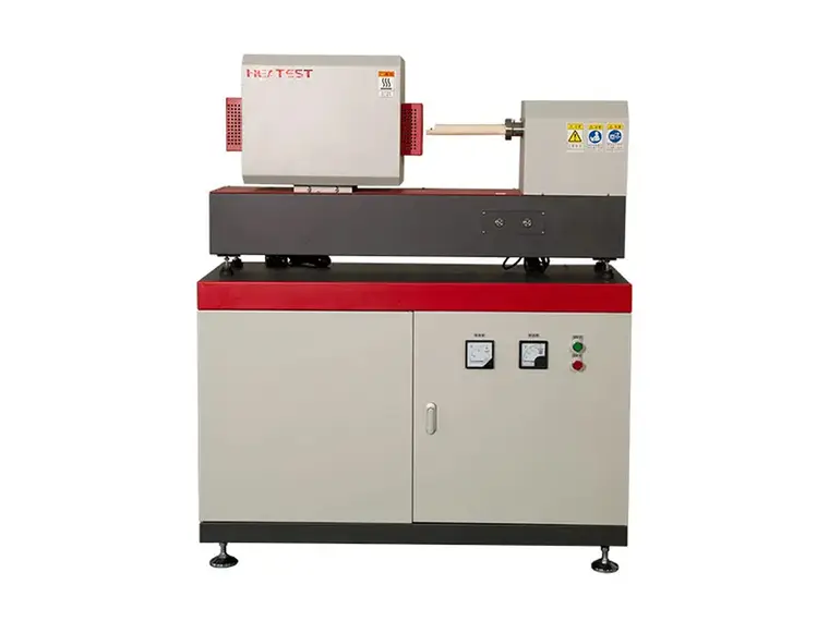
How to calculate the design of vibrating feeder

Vibrating feeder is a kind of equipment that uses the principle of mechanical vibration to make the working parts produce periodic motion, so as to transport materials. It is widely used in the power, building materials, coal mining, metallurgy, chemical industry, grain and other industries to transport various non-viscous bulk materials. Its design is a complex process involving multidisciplinary knowledge, which requires comprehensive consideration of multiple factors such as machinery, materials, dynamics, etc.Designing a vibrating feeder involves several key calculations to ensure that the feeder operates efficiently and effectively. Here is a step-by-step guide to help you with the calculations:

Vibrating feeder

1. Determine the Capacity

The capacity of a vibrating feeder is usually given in tons per hour (TPH). To determine the capacity:

Q=3600*A*V*D*w*efficiency

where:

Q = Capacity (TPH)

A = Cross-sectional area of the material bed on the feeder tray (m²)

V = Velocity of the material on the feeder tray (m/s)

D = Density of the material (kg/m³)

w = Width of the feeder tray (m)

efficiency = Efficiency factor (usually between 0.75 and 0.9)

2. Calculate the Cross-sectional Area (A)

The cross-sectional area can be calculated based on the shape and dimensions of the feeder tray:

A=Width×Height

3. Calculate the Velocity (V)

The velocity can be determined using the stroke and frequency of the feeder:

For more detailed information on vibrating feeder design calculation, please click here: https://www.zexciter.com/en/a/news/vibrating-feeder-design-calculation.html

What are the installation methods of vibrating screen mesh?

Vibrating screen mesh is a metal mesh structure element used for screening and filtering. It is widely used in screening, filtering, dehydration, desludging and other operations in many industries such as mining, coal mining, construction, glass factories, petroleum, hardware products, food processing, and medicine. It uses vibration waveforms to screen and classify materials on the screen to achieve separation of different particle sizes.

The weaving structure of the vibrating screen is diverse, including bidirectional corrugated bend, locking bend, bidirectional wave separation bend, flat top bend, unidirectional corrugated bend, etc. These structures make the screen strong and durable, able to withstand the huge impact and friction when the vibrating screen is working. The models and specifications of the screen are also diverse, such as flat screen plates, curved screens, etc., to meet the needs of different industries and application scenarios.The correct installation method of the vibrating screen is very important to ensure the screening effect and the service life of the screen.

Vibrating screen mesh installation methods

Vibrating screen mesh

1. Preliminary preparation

Check the screen: Make sure the screen is not damaged or deformed, and the size matches the screen frame.

Prepare tools: Prepare the tools required for installation, such as bolts, nuts, hooks, wooden wedges, hammers, etc.

Clean the screen frame: Clean the debris and residue on the screen frame to ensure that the surface of the screen frame is clean and free of impurities.

2. Installation steps

Open the dust cover and take out the screen frame: First, you need to open the dust cover of the vibrating screen, and then take out the screen frame that needs to be replaced or installed.

Fix the screen:

Bolt fixation: For screen plates with a thickness greater than 8mm or textile screens with a large screen wire diameter, bolts can be used to fix them directly to the screen frame. Bolts are in the form of U-type and J-type. J-type bolts are more convenient to disassemble, so they are more commonly used.

Hook tensioning: For woven screens or screen plates with a thickness of less than 6mm, the end of the screen or screen plate can be bent into a hook shape, and then fixed with hooks and bolts. In order to effectively tension the screen surface and not produce secondary vibration, the bolts should be designed in a certain angle and elastic washers should be added on the outside.

Slot structure: Some vibrating screens use slot structure to fix the screen plate. This method is easy to disassemble and replace, and is fast. It is suitable for thin steel plate punching screen surface, rubber and polyurethane screen surface for medium material screening.

For more detailed information about vibrating screen mesh installation, please click here: https://www.zexciter.com/en/a/news/vibrating-screen-mesh-installation-methods.html

What are the application areas of vibrating screen?

vibrating screen is a mechanical device used to separate materials based on size and shape. It works by using vibration to move materials across a screen or mesh, allowing finer particles to pass through while larger particles are retained. Common applications include mining, construction, and recycling industries.

Vibrating Screen Application

vibrating screen

Mining and Quarrying: Separating minerals and aggregates from ores and crushed materials.

Construction: Sifting materials for concrete production, sand and gravel separation.

Food Processing: Screening grains, seeds, and other food products for size and quality control.

Chemical Industry: Separating chemicals, powders, and granules for quality assurance.

For more detailed information about the application of vibrating screens, please click here: https://www.zexciter.com/en/a/news/vibrating-screen-application.html

How to maintain the vibrating screen exciter

Maintaining a vibrating screen exciter is crucial to ensure the efficient and smooth operation of the vibrating screen. Proper maintenance can extend the life of the equipment and prevent unexpected breakdowns.

Vibrating screen exciter maintenance

vibrating screen exciter

Regular Inspections

Visual Inspection: Regularly inspect the exciter and its components for any visible signs of wear, damage, or leaks.

Check Bolts and Fasteners: Ensure all bolts and fasteners are tight and secure. Vibrations can cause them to loosen over time.

Inspect Bearings: Check the condition of the bearings for signs of wear or damage. Ensure they are properly lubricated.

Lubrication

Follow Manufacturer’s Guidelines: Use the type and amount of lubricant specified by the manufacturer.

Regular Lubrication: Regularly lubricate the bearings and other moving parts as per the maintenance schedule.

Check Lubricant Levels: Ensure that lubricant levels are maintained within the recommended range.

Alignment and Balance

Check Alignment: Ensure that the exciter is properly aligned with the vibrating screen.

Balance Exciter: Ensure that the exciter is balanced to avoid uneven vibrations which can cause excessive wear and tear.

vibrating screen exciter

Cleaning

Keep Clean: Regularly clean the exciter and surrounding areas to prevent dust and debris build-up.

Check for Blockages: Ensure that there are no blockages in the lubrication passages.

Electrical Components

Inspect Wiring: Regularly inspect all electrical wiring and connections for signs of wear or damage.

Check Insulation: Ensure that the insulation on all wires is intact to prevent short circuits.

For more detailed information on vibrating screen exciter maintenance, please click here: https://www.zexciter.com/en/a/news/vibrating-screen-exciter-maintenance.html

Welding Rotator Operating Instructions

Welding rotators are used in various industries to facilitate the welding of cylindrical or round objects, such as pipes, tanks, and other similar structures. They provide support and rotate the workpiece, allowing the welder to work on a stationary weld head, ensuring uniform and consistent welds.

Welding Rotator Operating Instructions

Welding rotators

1. Safety Precautions

Personal Protective Equipment (PPE): Always wear appropriate PPE, including safety glasses, welding helmet, gloves, and protective clothing.

Work Area: Ensure the work area is clean, well-lit, and free from flammable materials.

Training: Only trained and authorized personnel should operate the welding rotator.

Inspection: Regularly inspect the rotator for any signs of wear or damage before use.

2. Pre-Operation Checks

Machine Condition: Inspect the welding rotator for any visible damage or wear. Check for loose bolts or connections.

Electrical Connections: Ensure all electrical connections are secure and the power supply matches the machine’s specifications.

Control Panel: Verify that all controls are functioning correctly and emergency stop buttons are operational.

Rollers and Bed: Check that the rollers are free from debris and are properly aligned. Ensure the bed is clean and free from obstructions.

3. Setup

Positioning the Workpiece:

Place the workpiece centrally on the rollers.

Adjust the distance between the rollers to fit the diameter of the workpiece.

Ensure the workpiece is balanced and stable on the rotator.

Aligning the Rotator: Align the rotator with the welding equipment to ensure smooth and consistent welding.

Securing the Workpiece: Depending on the weight and shape of the workpiece, secure it with straps or clamps if necessary.

Welding rotators

4. Operating the Welding Rotator

Power On: Turn on the power supply to the welding rotator.

Speed Adjustment: Adjust the rotation speed according to the welding requirements using the control panel.

Start Rotation: Begin rotating the workpiece at a low speed to check for balance and alignment. Gradually increase the speed as needed.

More detailed information about welding roller stand operation can be found at: https://www.bota-weld.com/en/a/news/welding-rotator-operating.html

What are the operating procedures of the circumferential seam welding machine?

Circumferential seam welding machine is an important automatic welding equipment, which is mainly used to complete the welding of various circular and annular seams.The circular seam welding machine is based on the principle of ordinary arc welding. It uses argon to protect the metal welding material. Through a large current, the welding material is melted into a liquid state on the welded substrate to form a molten pool, so that the welded metal and the welding material can achieve metallurgical bonding. Due to the continuous supply of argon during high-temperature melting welding, the welding material will not come into contact with oxygen in the air, thereby preventing the welding material from being oxidized. Therefore, stainless steel and ferrous metals can be welded.

Circumferential seam welding machine operating procedures

Circumferential seam welding machine

The operating procedures of the girth welding machine are important guidelines for ensuring that the welding process is safe, efficient and high-quality. The following are the operating procedures of the girth welding machine compiled from multiple sources:

1. Preparation before operation

Be familiar with the equipment:

The operator should be familiar with the basic structure, working principle and operating procedures of the girth welding machine.

Understand the meaning of the various functions, control buttons and indicator lights of the equipment.

Inspect the equipment:

Check whether the power cord and switch are normal, and ensure that there is no debris on the machine body and around it.

Check whether the relevant grounding wires and grounding devices of the welding equipment are reliable.

Check whether the cables, welding guns and welding parts are intact and there is no leakage or short circuit.

Prepare materials:

Confirm whether the required welding materials, tools, equipment, protective supplies, etc. are prepared in sufficient quantities.

Check whether the welding materials meet the requirements, including material, specifications, dimensions, etc.

Clear welding requirements:

Confirm the material, thickness, specifications, process and other requirements of the welding workpiece.

Select appropriate welding parameters and welding methods according to welding requirements.

For more detailed information on the operating procedures of the circumferential seam welding machine, please click here: https://www.bota-weld.com/en/a/news/circumferential-seam-welding-machine-operating-procedures.html

What is the process of storage tank welding production line?

storage tank welding production line is a specialized setup designed for the efficient manufacturing of storage tanks used in various industries, such as oil and gas, chemicals, water treatment, and food processing.

Key Components of Storage Tank Welding Production Line

Storage Tank Welding Production Line

Raw Material Preparation:

Sheets of steel or other materials are cut to size and prepared for welding.

Welding Stations:

Automated or semi-automated welding machines perform various types of welding (e.g., TIG, MIG, or submerged arc) to join tank components.

Assembly Line:

Components are assembled in a sequential manner to streamline production.

Inspection Stations:

Quality control measures, including visual inspection and non-destructive testing, ensure weld integrity and overall quality.

Finishing Area:

Tanks are finished through processes such as grinding, painting, or coating to enhance durability and corrosion resistance.

Storage and Logistics:

Finished tanks are stored or transported for installation or further processing.

Storage Tank Welding Production Line Production Process

Storage Tank Welding Production Line

Design and Planning:

Detailed plans are developed, often using CAD software, to specify dimensions and material requirements.

For more detailed information about the process flow of the tank welding production line, please click here: https://www.bota-weld.com/en/a/news/storage-tank-welding-production-line-process.html

What are the components of the gantry CNC welding machine?

gantry CNC (Computer Numerical Control) welding machine is a type of automated welding system designed for high precision and efficiency in welding operations. These machines are commonly used in industries such as automotive, aerospace, shipbuilding, and heavy machinery manufacturing.

Gantry CNC welding machine components

Gantry CNC welding machine

Gantry Frame:

The main structural component that moves the welding head along the X and Y axes.

Built from strong materials to withstand the forces and heat generated during welding.

CNC Controller:

The brain of the machine that controls all movements and welding parameters.

Can be programmed with specific welding paths and parameters for different jobs.

Welding Power Source:

Supplies the electrical energy needed for the welding process.

Can be adjusted to different power levels based on the welding requirements.

Welding Head/Torch:

The tool that performs the welding operation.

Can be equipped with different types of welding torches depending on the application.

Drive System:

Includes motors, drives, and transmission systems that move the gantry and welding head.

Often uses servo motors for precise control.

Cooling System:

Cools the welding head and other components to prevent overheating.

Can include water cooling or air cooling systems.

For more detailed information about the composition of the gantry CNC welding machine, please click here: https://www.bota-weld.com/en/a/news/gantry-cnc-welding-machine-composition.html

How to adjust the roller skin of the briquetting machine

The roller skin of the briquetting machine is an important part of the briquetting machine. It is located outside the roller core of the briquetting machine. It is usually a cylindrical component with a ball socket on its surface. The shape and size of these ball sockets are designed according to the pressed material and the required product shape. The adjustment of the roller skin of the briquetting machine is a key step to ensure the normal operation of the briquetting machine and improve the product quality.

Briquetting Machine Roller Adjustment

Briquetting Machine Roller

1. Adjustment method

Gap adjustment:

The gap of the roller skin determines the filling amount and molding pressure of the material. The appropriate gap can ensure that the material is evenly distributed between the roller skins and avoid molding problems caused by uneven pressure.

The gap between the roller skins is usually adjusted by adjusting the adjusting nut of the machine. The gap size needs to be adjusted according to the nature of the material and the molding requirements.

In general, the smaller the gap, the denser the molded balls, but too small a gap may cause the equipment to jam or block the material; too large a gap will cause the molding accuracy to decrease.

Parallelism verification:

Use tools and measuring equipment to check the parallelism of the roller skins and make fine adjustments until the two roller skins are completely parallel over the entire length. The guarantee of parallelism helps the material to be evenly stressed between the roller skins and improve the molding quality.

Pressure adjustment:

The pressure of the briquetting machine is usually achieved by adjusting the hydraulic cylinder or mechanical transmission system. The size of the pressure should be adjusted according to the nature of the material and the molding effect. Too low pressure will result in poor spherical quality, while too high pressure may increase the equipment load and energy consumption, and even damage the machine.

More detailed information about briquetting machine roller skin adjustment can be found at: https://www.zymining.com/en/a/news/briquetting-machine-roller-adjustment.html

How does the bucket elevator work?

Bucket elevator is a continuous conveying machine that uses a series of buckets evenly fixed on an endless traction member to vertically lift materials. It is widely used in many industrial fields and has a series of unique advantages and characteristics.

The working principle of bucket elevator is mainly based on the transmission of chain or belt, and the materials are lifted from low to high through a series of buckets. The following is a detailed description of the working principle:

Bucket elevator working principle

Bucket elevator

Bucket elevator is a device that uses transmission devices such as chains or belts to lift materials from low to high. Its working principle includes four main steps: loading, lifting, transmission and unloading of materials.

Specific steps

Loading:

The material is loaded into the bucket of the bucket elevator through the feed port. The bucket is the main loading component of the bucket elevator, which is responsible for loading and temporarily storing materials.

Lifting:

When the drive device (usually composed of a motor, a reducer, a coupling, etc.) is started, it generates power and transmits it to the bucket through a transmission device (chain or belt).

The bucket rises along the body driven by the transmission device, lifting the material from low to high. In this process, the chain plate or belt plays a role in stabilizing the transmission of materials and reducing material wear.

Transmission:

As the bucket rises, the material is stably transmitted to a high place. The rotation speed of the chain plate or belt is indirectly controlled by the reducer, so that the material can be kept continuous, accurate and stable during the transmission process.

Discharging:

When the hopper reaches the top, it will encounter the discharge port. At this time, the hopper will open or tilt in some way to discharge the material from the hopper, completing the lifting and transportation process.

The unloading process can be achieved through auxiliary devices such as diversion nozzles to ensure that the material is transported to the destination at a uniform speed.

Structural composition

Bucket elevator

The bucket elevator is mainly composed of the following main components:

Feeding hopper: a container for loading materials.

For more detailed information about the working principle of bucket elevator, please click here: https://www.zymining.com/en/a/news/bucket-elevator-working-principle.html