Maintenance tips for slewing bearings of wheeled cranes

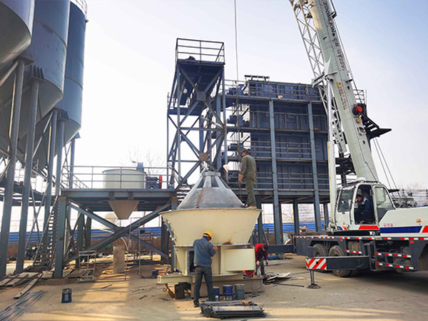
The slewing bearing of the wheeled crane is an important “joint” of the crane, so its maintenance is very important. When carrying out maintenance work, the first thing to be aware of is the risk of being dragged into the rotating pinion, crushing and shearing. When performing the following tasks, ensure that no maintenance personnel are in the danger zone between the main boom, upper carriage and roller, or between the lower carriage and roller when starting the engine to perform the necessary swing and luffing movements. Hazardous area, except for the crane operator (in the cab).

Wheeled Crane Maintenance

slewing bearings of wheeled cranes

1. Check the bolts of the slewing bearing

Before each crane work or at least once a week, check the bolts on the slewing bearing; after the first 100 working hours of the slewing bearing, check whether the bolts are loose, and then check again at the 300th working hour; check every 500 working hours thereafter Once; in severe working conditions, the inspection interval should be shortened.

When replacing bolts, first wipe the bolts clean, apply thread fastening glue and then tighten them; check the fastening bolts regularly to avoid the danger of bolt fatigue damage;

If the bolts are found to be loose during the inspection, please stop the construction work, and immediately contact the local after-sales service engineer, and let a professional inspect it to decide whether to disassemble and inspect immediately.

For details, click to visit:https://www.excavatorbearing.com/a/bearing-knowledge/wheeled-crane-slewing-bearing-maintenance.html

The structure and maintenance method of steel wire raceway bearing

Steel wire raceway bearings can also be called steel wire raceway bearings and steel wire bearings. As a new type of non-standard bearing, it has light weight and high rotation accuracy. The ability to carry both axial force and radial force has been widely used in the support of large-load, low-inertia, and large-diameter bearings. Steel wire raceway bearings can completely replace ordinary light-duty slewing bearings in certain usage occasions, and achieve the use effect that ordinary slewing bearings cannot achieve. Steel wire raceway bearing manufacturers have summarized the structure and maintenance methods of steel wire raceway bearings, let’s find out together.

The structure of steel wire raceway bearings

The structure of the steel wire raceway (runway) bearing is a structure surrounded by three entities. It generally consists of a fixed large table main body, a movable syringe seat gear and a compression ring, which enclose a square-section steel wire raceway bearing in the middle. If the steel ball in the square section is used as the center of the structure, then according to the position of the pressing ring relative to the steel ball and the center of the syringe, this support structure can be divided into: upper inner pressing ring type; upper outer pressing ring type; Ring type; lower inner pressure ring type; lower outer pressure ring type four forms.

However, in terms of the convenience of adjusting and replacing the steel wire raceway bearing, it is an example of all three solid surrounding steel wire raceway bearing structures. This structure is not only very convenient to adjust the gap of the steel wire raceway bearing, just loosen the screw and replace the thickness of the gasket. Moreover, when the steel wire raceway bearing needs to be replaced, the compression ring can be easily removed without removing any other parts, and a new steel wire raceway bearing can be reinstalled quickly.

Structural parameters of steel wire raceway bearings

Name Unit Structural Parameters
Nominal inner diameter mm 457
Nominal outer diameter mm 483
Diameter mm 9.52
Radius of curvature of inner ring steel wire mm 2
Inner raceway diameter mm 461.08
Radius of curvature of outer ring steel wire mm 2
Outer raceway diameter mm 478.94
initial contact angle a 45°
Elastic modulus E of steel wire and steel ball GPa 206
Steel wire and steel ball Poisson’s ratio γ 0.3
total radial load N 838.8.

For details, click to visit:https://www.prsbearings.com/a/news/structure-of-wire-raceway-bearings.html

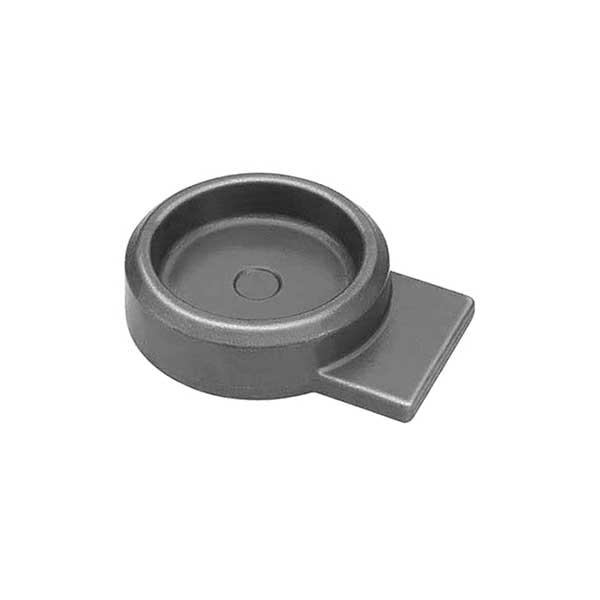
ANALYSIS OF TECHNICAL CHARACTERISTICS OF FORGED SHAFT FORGINGS

Forging is a processing method that uses forging machinery to apply pressure to metal blanks to cause plastic deformation to obtain shaft forgings with certain mechanical properties, certain shapes and sizes. Forging and stamping belong to the nature of plastic processing, collectively referred to as forging. Forging is a common forming method in mechanical manufacturing. The as-cast looseness and welding holes of the metal can be eliminated by forging, and the mechanical properties of forgings are generally better than castings of the same material. For important parts with high load and severe working conditions in machinery, forgings are mostly used except for plates, profiles or weldments that can be rolled with simple shapes.

The recrystallization temperature of steel is about 460°C, but 800°C is generally used as the dividing line, and hot forging is above 800°C; it is called warm forging or semi-hot forging between 300 and 800°C.

Forging can be divided into cold forging and hot forging according to the temperature of the blank during processing. Cold forging is generally processed at room temperature, and hot forging is processed at a temperature higher than the recrystallization temperature of the blank metal. Sometimes it is also called warm forging when it is heated but the temperature does not exceed the recrystallization temperature. However, this division is not completely uniform in production.

For details, click to visit:https://www.gold-emperor.com/technology-of-forging-shaft-forgings/

How does the self-loading garbage truck work?

Self-loading garbage truck is a kind of garbage truck that has a very large demand in the sanitation vehicle market in recent years. This model is used in conjunction with plastic square drums or iron drums for the collection and transfer of urban domestic garbage trucks. The hanging bucket garbage truck is small in size, easy to operate, and has the function of self-loading and self-unloading, which greatly reduces the labor intensity of sanitation workers. It is very suitable for use in areas with narrow roads such as residential areas, streets, and rural areas.

Working status of self-loading garbage truck

One of the most notable features of the self-loading garbage truck is that the garbage bin full of garbage is lifted by the garbage bin lifting mechanism and automatically dumped into the box of the pull-through garbage truck. Today we will introduce the lifting mechanism of the self-loading garbage truck.

Self-loading Garbage Truck

The lifting mechanism of the self-loading garbage truck is mainly composed of hydraulic cylinders, lifting arms, pull rods, lifting frames, turning frames, rockers, rollers and guide rails.

When the self-loading garbage truck needs to load garbage, the control handle of the hydraulic cylinder is moved, the hydraulic system provides power through the hydraulic pump, and the piston rod of the hydraulic cylinder is pushed out, and the lifting arm rotates around the distance between it and the box under the thrust of the piston rod. The hinge point swings, and the lifting arm drives the pull rod to move upwards, and then drives the lifting frame with the trash can to move upwards along the secondary guide rail of the reversing frame until the trash can touches the pressing plate on the reversing frame, and drives the reversing frame to move upwards along the main rail.

When the rollers at the upper end of the turning frame move to the end of the curved track at the top of the main rail, the upper rollers are blocked and stop, and at the same time, the pull rod continues to pull up the lifting frame, so that the axis line of the upper rollers of the turning frame is the turning axis to turn over the trash can until the trash can is finished. Garbage is automatically dumped.

Self-loading Garbage Truck

After the garbage is emptied, oil is reversely fed through the double-acting hydraulic cylinder, and the piston rod starts to retract. The lifting arm swings in the opposite direction, so that the garbage can returns to the initial position, and the working process of automatically filling garbage is completed.

Self-loading garbage trucks not only have a wide range of functions, but also have strong scalability. Add a compression push plate to the box of the self-loading garbage truck to become a compressed self-loading garbage truck. Add filter plate in the box, it can be used as a kitchen garbage truck. In addition, we can also add a weighing function to the self-loading garbage truck to detect the amount of garbage collected and so on.

For more details about self-loading garbage trucks, please click to visit: https://www.ly-cimc-linyu.com/sanitation-truck/self-loading-garbage-truck.html

Process steps of forging shaft forgings

Shaft forgings are metals formed by forging and pressing after solid-state heating. It requires the metal to have good thermoplasticity. Generally, shaft forgings are steel parts. It has high strength and good plasticity, and is suitable for manufacturing important parts with high stress and high requirements. Such as bolts, shafts, gears, etc.

The specific steps of the forging process are as follows:

Material calculation and blanking are one of the important links to improve the utilization rate of materials and realize the refinement of blanks. Excessive material not only causes waste, but also increases cavity wear and energy consumption. If there is no allowance for blanking, it will increase the difficulty of process adjustment and increase the scrap rate. In addition, the quality of the blanking end face also has an impact on the process and the quality of the shaft forging.


The purpose of heating is to reduce the forging deformation force and improve metal plasticity. But heating also brings a series of problems, such as oxidation, decarburization, overheating and overburning. Accurate control of the initial forging and final forging temperature has a great influence on the structure and performance of the product.

Flame furnace heating has the advantages of low cost and strong applicability, but the heating time is long, oxidation and decarburization are easy to occur, and the working conditions need to be continuously improved. Electric induction heating has the advantages of rapid heating and less oxidation, but it has poor adaptability to changes in product shape, size and material.

Forging forming is produced under the action of external force. Therefore, correct calculation of deformation force is the basis for selecting equipment and performing mold check. Stress-strain analysis of the deformed body is also indispensable for optimizing the process and controlling the microstructure and properties of the shaft forging.

Therefore, the quality analysis of shaft forgings can generally be divided into the stage of on-site investigation, the stage of experimental research and analysis, the stage of proposing solutions and prevention countermeasures. Before implementing these stages of work, it is best to formulate an implementation plan, including the tasks, work procedures, and completion time of these three stages. Appropriate additions and modifications can be made to this embodiment during implementation. Making an implementation plan is an important part of analyzing the quality problems of large and complex shaft forgings and used parts.

How to maintain the truck crane slewing bearing?

The truck crane slewing bearing is an important “joint” of the crane, so its maintenance is very important. So how to maintain the truck crane slewing bearing?

When carrying out maintenance work, the first thing to be aware of is the risk of being dragged into the rotating pinion, crushing and shearing.

When performing the following tasks, ensure that no maintenance personnel are in the danger zone between the main boom, upper carriage and roller, or between the lower carriage and roller when starting the engine to perform the necessary swing and luffing movements. Hazardous area, except for the crane operator (in the cab).

Check the bolts of the truck crane slewing bearing

1. Before the crane works each time or at least once a week, visually check the bolts on the slewing bearing;

2. After the first 100 working hours of the slewing bearing, check whether the bolts are loose, and then check again at the 300th working hour; after that, check every 500 working hours; shorten the inspection interval for severe working conditions. If the bolts are found to be loose during the inspection, please stop the construction work and contact the local after-sales service department immediately, and the factory or professional technicians will inspect and decide whether to dismantle and inspect immediately;

3. The slewing bearing is filled with lithium-based grease before installation;

crane slewing bearing

4. When replacing the bolts, wipe the bolts clean, apply thread fastening glue and then tighten them; use a crane according to the requirements of the operation manual and lifting performance table, or check the fastening bolts regularly according to the requirements, so as to avoid fatigue damage of the bolts Danger;

Routine inspection of truck crane slewing bearing

1. Regularly check the flexibility of rotation; if noise and impact are found, stop the machine immediately for inspection, troubleshoot, and disassemble if necessary;

2. Regularly check whether the rotary ring gear is cracked or damaged, and whether the meshing tooth surface has bite, gnawing, tooth surface peeling, etc.;

3. Regularly check the integrity of the seal. If the seal is found to be damaged, it should be replaced in time, and if it is found to be falling off, it should be reset in time.

excavator slewing bearing

Lubricate the tooth surface of the truck crane slewing bearing

The ring gear of the slewing ring has been coated with anti-rust oil before leaving the factory. The validity period of this anti-rust is generally 3 to 6 months. After the expiration date, it should be coated with anti-rust oil in time.

In addition, in use, prevent the slewing bearing from being exposed to direct sunlight. It is forbidden to wash the slewing bearing directly with water, so as to prevent water from entering the raceway, and strictly prevent hard foreign objects from approaching or entering the meshing area of the teeth.

More detailed information on truck crane slewing bearings can be accessed by clicking: https://www.excavatorbearing.com/Slewing-bearing-for-truck-crane.html

Causes and treatment methods of oil leakage of harmonic reducer bearing end cover

Harmonic reducer bearings are produced for matching harmonic reducers. They are compact in shape and have mounting holes for easy installation. They are suitable for various types of harmonic reducers. Oil leakage from the end cover of harmonic reducer bearings is also common. In response to this problem, relevant personnel have summarized the causes and treatment methods of oil leakage, let’s take a look~

Causes of oil leakage from the bearing end cover of the harmonic reducer

1. For the oil leakage of the non-shaft extension cover, the main reason is that the gap between the end cover and the box body is relatively large.

2. The main reasons for the oil leakage of the end cover of the shaft extension are that the gap between the end cover and the box is large, the input or output shaft and the inner hole of the end cover are missing or the seal is damaged, the vent plug is blocked, and the oil level is too high.

The treatment method of oil leakage of the bearing end cover of the harmonic reducer

crossed roller bearings

1. For the non-shaft extension cover, it can be reprocessed to reduce the gap. Before installation, apply even sealant on each connection surface and press it tightly. leak.

2. For the bearing cover of the shaft extension, in addition to ensuring the gap between the end cover and the joint surface of the box body, sealing elements and oil drainage plates should be added to the end cover.

3. Add a drainage plate on the inner side of the bearing close to the tank wall, so that the oil thrown on the drainage plate can be drained into the oil pool.

4. The rotation range of the drainage plate in the bearing may be very large. In order to further prevent leakage, a felt sealing ring can be added in the end cover, and the same drainage hole as the fish felt groove can be set on the end cover, even if the oil leaks Into the felt ring, the centrifugal effect can also drain it into the box through the drainage hole, thus effectively cutting off the leakage channel.

5. There is a ventilator installed on the harmonic reducer. If the vent hole is blocked, the temperature of the box will rise, the gas will expand, and the pressure will increase, which will aggravate the oil leakage. Therefore, it is necessary to ensure that the vent hole is not blocked, so that The internal and external pressure of the reduction box is balanced, which can effectively prevent leakage.

6. The increase of oil resistance will reduce the efficiency of the machine, so the amount of oil added must be appropriate, and the depth of the gear in the oil cannot exceed the height of another tooth, because the oil is stirred violently, which will increase the oil temperature and accelerate leakage.

The above article describes in detail the solution to the oil leakage of the bearing end cover of the harmonic reducer. It is worth noting that when selecting the felt ring, the size must be based on the size of the felt groove and the diameter of the shaft. Pay attention to ensure that The tolerance of the shaft and the content of the felt ring is matched, so that the oil leakage of the bearing end cover can be effectively prevented.

More information about harmonic reducer bearings can be accessed by clicking:https://www.prsbearings.com/Harmonic-reducer-bearing/Harmonic-reducer-flexible-bearing.html

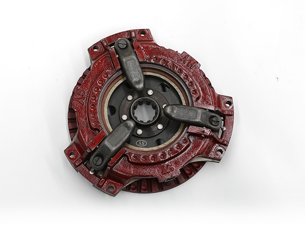
What are the points for attention in the operation of Kubota tractor driving clutch

Points for attention in the operation of the main transmission lever of the clutch of Kubota tractor

The main gear lever is partially synchronized, so it can be switched between 3rd and 4th gears and 7th and 8th gears when the tractor is moving.

When switching, you only need to depress the clutch and move the shift lever, without stopping the machine completely.

But when shifting between 1st and 2nd gears and between 5th and 6th gears, you need to step on the clutch and stop the tractor before shifting gears.

tractor clutch

Important:

To avoid damage to the transmission, depress the clutch pedal and stop the tractor before shifting between gears.

Notes on the use of Kubota tractor clutch

1. Before each use, please confirm the play of the travel clutch pedal, depress the travel clutch pedal slightly, and measure the play at the top of the pedal stroke.

The correct clutch pedal clearance is 35-45mm on the pedal

Note:

If the play is not within specification, loosen the lock nut and turn the turnbuckle to adjust the length of the screw within the allowable limits.

1. Check, adjust, and confirm for the first 50 hours, and check, adjust, and confirm every 100 hours thereafter.

2. When reversing forward and backward, ensure that the tractor is in a stationary state, and step on the clutch to operate the reversing handle to avoid early damage to the driving clutch.

3. When switching between high and low gears, ensure that the tractor is in a stationary state and the other handles are in neutral positions, and then switch by stepping on the driving clutch.

4. When the tractor is working and walking, avoid using the half-clutch state to avoid early wear of the driving clutch.

Note: Due to the design changes of the product, please refer to the instruction manual of the vehicle product for details.

For more details about Kubota Tractor Clutch, please click to visit:https://www.syclutch.com/tractor-clutch/tractor-clutch-kit/k-series

What are the characteristics of the mobile vertical grow racks?

The mobile vertical grow rack includes a planting tank and a movable growing frame. There are several uprights fixed on the edge of the planting tank. The upper ends of the uprights are fixedly connected by crossbeams. For the movable growth frame, the upper part of the column is also provided with a support rod for supporting the movable growth frame in an inclined upward direction. The mobile vertical grow rack has the advantages of simple structure, good lighting, good ventilation, and not easy to grow insects, etc., which can effectively improve the growth and yield of plants, and can conveniently solve the problem of plants keeping out of the cold and overwintering.

1. The mobile vertical grow rack is characterized in that the planting frame includes a planting tank and a movable growing frame, and several uprights are fixedly arranged on the edge of the planting tank, and the upper ends of the uprights are fixed by beams connect, the upper movable sleeve of crossbeam is provided with sleeve pipe, is fixedly provided with movable growth frame on the sleeve pipe, and the top of column is also provided with the pole that is used to support movable growth frame to the direction of inclination upward.

2. The mobile vertical grow rack is characterized in that the columns are symmetrically arranged in pairs on the two short edges of the planting groove, and each short edge is provided with two columns, which are combined into two pairs of symmetrically arranged uprights.

vertical growth racks

3. The mobile vertical grow rack is characterized in that the upper ends of the two pairs of symmetrically arranged columns are fixed with the beams, and there are two mobile vertical grow racks, and the movable growing frames are respectively arranged on the two on the above-mentioned crossbeam, and two movable growth frames are arranged to cross each other.

4. The mobile vertical grow rack is characterized in that the support rod is a “shaped structure, its vertical long end is fixedly arranged on the upper end of the column, and its horizontal short end is higher than the height of the column. The frame of the mobile vertical grow rack leans against the horizontal short end to support the movable growth frame in an inclined upward direction.

5. The mobile vertical grow rack is characterized in that the upper ends of the first pair of two columns symmetrically arranged are fixed with the beams, the movable growing frame is arranged on the beams, and the second pair of symmetrically arranged The height of the upper ends of the two uprights is higher than that of the first pair of uprights, the upper ends of the second pair of uprights are provided with transverse struts, and the higher parts of the upper ends of the second pair of uprights are combined with the transverse struts to form the struts.

6. The mobile vertical grow rack is characterized in that the movable growing frame includes a movable beam and several rows of rattan racks arranged on the movable beam, and the movable beam is fixedly connected with the casing.

vertical growth racks

7. The mobile vertical grow rack is characterized in that a reinforcing beam is fixedly connected between the two columns.

8. The mobile vertical grow rack is characterized in that the two ends of the beam are respectively set with the sleeves, each of the sleeves is provided with the movable beam perpendicular to the beam, and the two movable beams on the same beam The front ends of the beams are connected to each other through fixed cross bars, and several rows of rattans are arranged between the two movable beams.

9. The mobile vertical grow rack is characterized in that the planting groove is made of cement concrete, and several through holes are arranged at the bottom.

10. The mobile vertical grow rack is characterized in that several rows of racks are arranged between the uprights.

The above is the full introduction of the characteristics of the mobile vertical grow rack. Only by understanding its characteristics in detail can the planting rack be used correctly and the problem of plant protection from the cold and overwintering can be better solved.

More information about mobile vertical grow racks can be accessed by clicking:https://www.etegreen.com/vertical-grow-rack-systems/mobile-vertical-grow-racks/

Process flow of high-speed automatic square bottom unit

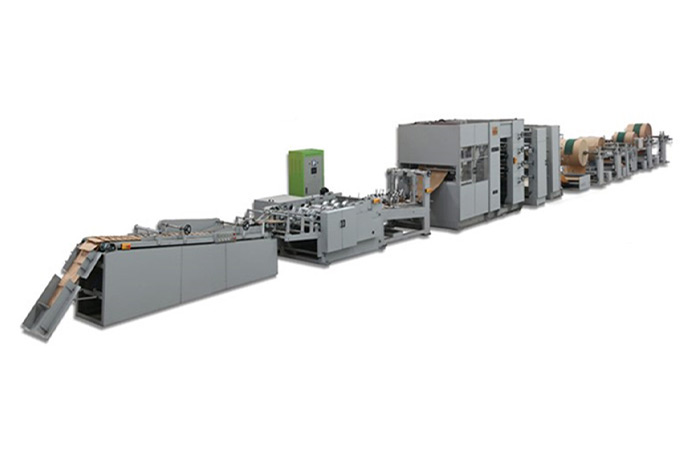
The high-speed automatic square bottom unit is a high-tech automatic assembly line production, mainly composed of ZT500 paper tube machine and HD300 bottom paste machine. Using the integration of light, machine, electricity and gas, there are more than 20 technological processes in total, and the computer programming PLC photoelectric program automatic control system is completed. This machine is currently domestically designed with high automation, good safe operation performance, high-speed automatic square bottom unit assembly line production, the whole machine lubrication system adopts automatic lubrication, the unit has good stability, low noise and low noise, and is easy to operate and adjust.

square bottom machine

(1) Process flow of paper tube machine

Unwinding, automatic overprinting, brake feeding and layer guidance, automatic unwinding and deviation correction, auxiliary traction, virtual cutting, horizontal step dispensing, longitudinal dispensing, bag tube forming, traction, piercing vents, tearing, separation send bag.

square bottom machine

(2) Process flow of square bottom machine

Rotary vacuum high-speed feeding, vent hole piercing, bag bottom forming, bag tube conveying, bag tube bottom opening, valve mouth strip pasting, automatic glue application, forming bottom sticking, bag bottom flipping, counting grouping, and stacking.
The above is the entire introduction of the process flow of the square bottom unit. I hope it can help you better, so that you can have a better understanding of the square bottom unit.