Analysis on the causes of briquetting machine not removing balls

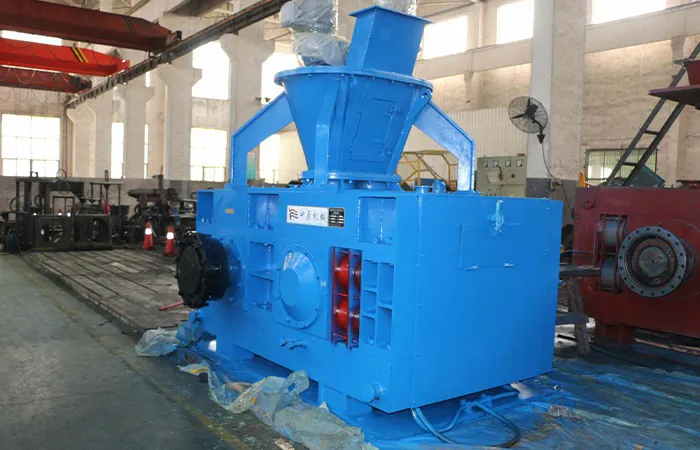
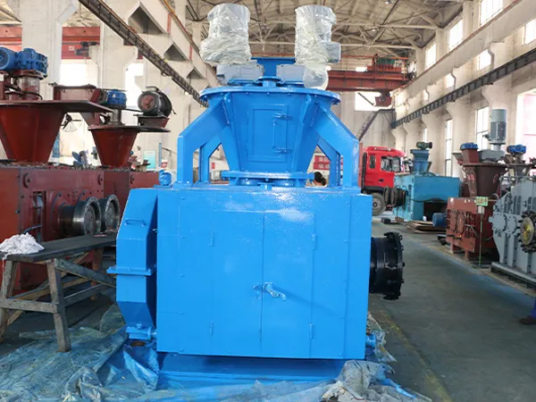
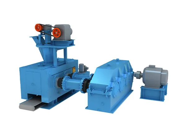
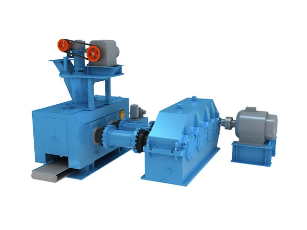
The main reasons why the briquetting machine does not remove the balls include excessive moisture content of the material, insufficient pressure strength of the ball embryo, rough surface of the new ball socket, misalignment of the ball socket, improper gap between the rollers, improper speed of the rollers, improper control of material moisture, improper use of material adhesives, etc. ‌For the problem of the briquetting machine not removing the balls, we have made a detailed summary for you, let’s take a look.

Reasons for the briquetting machine not to remove the balls

briquetting machine

1. Inadequate Material Moisture Content

Problem: If the raw material’s moisture content is either too high or too low, it can affect the briquette formation and removal.

Cause: High moisture makes the material too sticky, causing it to adhere to the rollers, while low moisture may lead to insufficient binding, causing the briquettes to crumble.

Solution: Adjust the moisture content to the optimal level recommended for the specific material being used.

2. Worn or Damaged Rollers

Problem: The rollers in a briquetting machine compress the material into briquettes. If they are worn out or damaged, the material may not compress correctly, leading to poor briquette formation.

Cause: Over time, the constant pressure and abrasion can wear down the rollers or create grooves and pits on their surface.

Solution: Regularly inspect and maintain the rollers. Replace or refurbish them if they show significant wear or damage.

3. Improper Roller Alignment

Problem: Misalignment of the rollers can cause uneven pressure distribution, leading to incomplete or poor briquette formation.

Cause: Misalignment can occur due to improper installation, mechanical issues, or wear and tear over time.

Solution: Check and realign the rollers according to the machine’s specifications. Regular maintenance is key to preventing this issue.

briquetting machine

4. Inadequate or Excessive Feeding

Problem: The feeding mechanism controls the amount of material entering the machine. Inadequate feeding can lead to underfilled briquettes, while excessive feeding can cause material overflow and jamming.

Cause: Incorrect settings, blockages in the feeding system, or inconsistent material flow can cause feeding issues.

Solution: Adjust the feeding mechanism to ensure a consistent and appropriate material supply. Clear any blockages and ensure smooth material flow.

For more detailed information about the reasons why the briquetting machine does not produce balls, please click to visit: https://www.zymining.com/en/a/news/reasons-for-the-briquetting-machine-not-to-remove-the-balls.html

How does the plate conveyor work?

A plate conveyor is a type of conveyor system specifically designed to transport flat, large, or heavy materials, such as metal plates, sheets, or panels, through various stages of a manufacturing or assembly process. Plate conveyors are commonly used in industries like automotive, metalworking, and heavy manufacturing.

Plate conveyor working principle

Plate Conveyor

1. Design and Components:

Conveyor Bed: The conveyor bed is the surface on which the plates or materials are placed. It consists of a series of linked or interconnected plates, often made of steel or other durable materials, forming a continuous, flat surface.

Drive System: The drive system powers the conveyor, typically consisting of an electric motor connected to a gearbox and drive chain or belt. The drive system moves the plates along the conveyor bed.

Rollers or Chains: Underneath the conveyor bed, rollers or chains help to support the weight of the plates and facilitate their smooth movement along the conveyor.

Guides and Sidewalls: These components ensure that the plates remain aligned on the conveyor bed and prevent them from sliding off during transport.

Control System: The conveyor’s operation is managed by a control system that regulates the speed, direction, and timing of the conveyor’s movement. This system may include sensors, switches, and other control devices.

2. Operation Process:

Loading the Plates:

Plates or flat materials are loaded onto the conveyor bed. This can be done manually, with the help of a crane, or through an automated feeding system, depending on the size and weight of the plates.

Conveyor Movement:

Once the plates are loaded, the conveyor begins moving them along the length of the system. The movement can be continuous or indexed (moving in steps), depending on the application.

Transportation of Materials:

The plates are transported from one end of the conveyor to the other. Along the way, they might pass through different workstations where various operations like cutting, welding, coating, or inspection take place.

Stopping and Positioning:

The conveyor can be programmed to stop at specific intervals, allowing for precise positioning of the plates for processing. For example, the conveyor might stop to allow a robotic arm to perform a welding operation, then continue moving once the task is completed.

Unloading the Plates:

At the end of the conveyor, the plates are unloaded. This can be done manually or through an automated system, such as a robotic arm or another conveyor that takes the plates to the next stage of production.

Plate Conveyor

3. Types of Plate Conveyors:

Flat Plate Conveyors: These are the most basic type, featuring a flat, continuous surface made of metal plates. They are ideal for transporting heavy and large items.

Slat Plate Conveyors: Slat conveyors have individual slats (plates) attached to chains. These are often used for handling large, heavy, or awkwardly shaped items that need to be kept in a stable position during transport.

For more detailed information about the working principle of plate conveyor, please click here: https://www.zymining.com/en/a/news/plate-conveyor-working-principle.html

What is the vibration standard of ring hammer crusher?

The vibration standard of ring hammer crusher is formulated according to the national mechanical vibration standard and the technical conditions and use requirements of the crusher. The specific standards may vary depending on the manufacturer, model and use environment. The following are some common vibration standards and their related points:

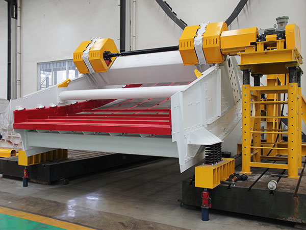
Ring hammer crusher vibration standard

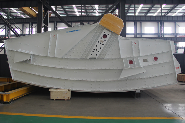
ring hammer crusher

1. Vibration index

The vibration of hammer crusher mainly comes from rotating parts (such as rotor and hammer), crushed materials and transmission system. In order to evaluate the intensity and impact of its vibration, the commonly used vibration indexes include:

Vibration velocity (mm/s): a comprehensive index reflecting the amplitude and frequency of the vibration source.

Acceleration (m/s²): a vibration signal in the form of a continuous waveform, used to reflect the amplitude of the vibration source.

Displacement (μm): the maximum displacement generated by the vibration source in a certain direction per unit time.

2. Vibration standard

For the vibration of hammer crusher, the commonly used evaluation standards include:

Vibration velocity evaluation standard: the vibration velocity measured on the bearing or structure should comply with the corresponding national or local first-level mechanical vibration standard.

Acceleration evaluation standard: similarly, the vibration acceleration measured on the bearing or structure should also comply with the corresponding standard.

Displacement evaluation standard: For displacement, the equipment without shock-absorbing platform is generally controlled below 120 microns (double amplitude), while the equipment with shock-absorbing platform is controlled below 200 microns (double amplitude). But please note that this standard may vary depending on the manufacturer and specific equipment.

ring hammer crusher

3. Vibration control method

In order to ensure the normal operation and service life of the ring hammer crusher, its vibration needs to be effectively controlled and repaired. Common control methods include:

Strengthen maintenance: Regularly inspect and maintain the crusher to ensure the balance and rationality of its rotating parts and transmission system, and reduce the intensity and frequency of the vibration source.

Optimize structure: Reduce the inherent vibration of the vibration source and conduction system by optimizing the structure and assembly of the crusher.

Adjust process: Reduce the inherent vibration of the vibration source and conduction system by adjusting and controlling the process parameters such as the crusher’s transmission system, material feeding and discharging.

More detailed information about the vibration standard of hammer crusher can be found at: https://www.zymining.com/en/a/news/ring-hammer-crusher-vibration-standard.html

What are the components of the welding positioner?

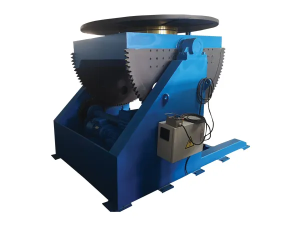
welding positioner is a device used to hold and rotate a workpiece to the optimal position for welding. It allows the welder to work at a consistent angle, improving weld quality, reducing fatigue, and increasing productivity. A welding positioner consists of several key components designed to hold, rotate, and tilt workpieces to facilitate welding from optimal angles.

Welding positioner composition

welding positioner

1. Rotating Table/Chuck

Rotating Table: The flat surface or platform where the workpiece is mounted. It rotates to allow access to different areas of the workpiece without manually repositioning it.

Chuck: A clamping device on the rotating table that securely holds the workpiece in place during rotation. Chucks can be three-jaw, four-jaw, or specially designed for specific workpiece shapes.

2. Tilt Mechanism

Tilting Table: Allows the rotating table or chuck to be tilted at various angles, providing the flexibility to position the workpiece optimally for welding.

Tilt Motor/Gears: Motor and gears control the tilting action, allowing precise adjustments to the tilt angle.

3. Control System

Control Panel: The interface used to control the rotation speed, tilt angle, and other positioner functions. It may include buttons, switches, or a touchscreen.

Foot Pedals/Remote Control: Optional control devices that allow the welder to adjust the positioner hands-free or from a distance.

4. Base Frame

Base/Frame: The sturdy structure that supports the positioner and ensures stability. It must be strong enough to bear the weight of the workpiece and resist vibration during operation.

welding positioner

5. Fixture Clamps

Clamps/Fixtures: Devices used to hold the workpiece securely to the rotating table or chuck. These can be adjustable to accommodate different shapes and sizes of workpieces.

6. Drive System

Rotation Motor: Powers the rotation of the table or chuck, allowing continuous or indexed rotation of the workpiece.

For more detailed information about the welding positioner, please click here: https://www.bota-weld.com/en/a/news/welding-positioner-composition.html

How to use the butt joint longitudinal seam welding machine

butt joint longitudinal seam welding machine is a specialized piece of equipment used to weld the longitudinal seams of cylindrical or tubular workpieces, such as pipes, tanks, or pressure vessels. This type of machine is designed to produce a continuous, high-quality weld along the entire length of the seam, ensuring strong and durable joints.Using a butt longitudinal seam welding machine involves several steps to ensure a proper and efficient welding process.

Butt joint longitudinal seam welding machine operation guide

butt joint longitudinal seam welding machine

1. Preparation

Safety Gear: Wear appropriate personal protective equipment (PPE), including welding gloves, goggles, apron, and helmet.

Material Preparation: Ensure the materials to be welded are clean, free from rust, oil, or other contaminants that could affect the weld quality.

Machine Setup: Adjust the machine settings based on the material type, thickness, and the required welding specifications. This includes setting the appropriate welding current, voltage, and speed.

2. Loading the Material

Positioning: Place the material into the machine, aligning the edges that need to be welded. The material should be securely clamped in place to prevent movement during welding.

Edge Alignment: Ensure that the edges to be welded are properly aligned. Misalignment can lead to poor weld quality or defects.

3. Welding Process

Starting the Machine: Initiate the welding process by starting the machine. The electrodes or welding torch will move along the seam, applying heat and pressure to join the edges.

Monitoring: Keep an eye on the welding process. Monitor the seam to ensure the weld is consistent and that there are no gaps or defects.

Adjustments: If needed, make real-time adjustments to the welding speed, pressure, or current to maintain weld quality.

butt joint longitudinal seam welding machine

4. Post-Welding

Inspection: Once the weld is complete, inspect the seam for any defects such as cracks, porosity, or incomplete fusion. Use visual inspection or non-destructive testing methods as necessary.

For more detailed information about the butt joint longitudinal seam welding machine use, please click here:https://www.bota-weld.com/en/a/news/butt-joint-longitudinal-seam-welding-machine-use.html

What are the main functions of the lead screw welding rotator?

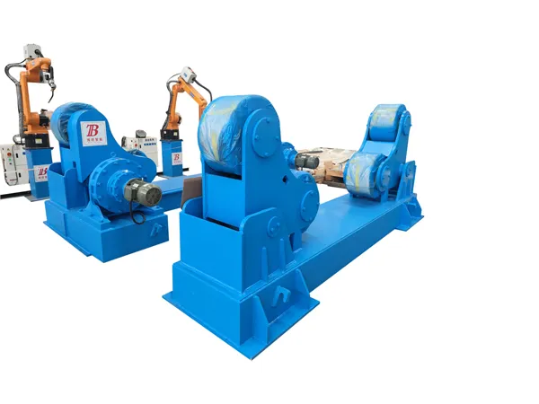
lead screw welding rotator is a specialized piece of equipment used in welding processes to support and rotate cylindrical workpieces, such as pipes, tanks, or pressure vessels, during welding. The use of a lead screw mechanism allows for precise adjustment of the position and alignment of the workpiece.

Lead screw welding rotator functions

lead screw welding rotator

1. Support and Stability of Workpieces:

The primary function of a lead screw welding rotator is to provide stable support for cylindrical workpieces during welding. The rotator’s rollers cradle the workpiece, preventing it from shifting or vibrating, which ensures a consistent weld.

2. Controlled Rotation:

The rotator allows for the controlled rotation of the workpiece. This rotation can be adjusted to the desired speed, which is crucial for achieving uniform welding around the circumference of the workpiece. The rotation speed can be fine-tuned depending on the welding requirements.

3. Precise Positioning and Alignment:

The lead screw mechanism enables precise positioning and alignment of the workpiece. By adjusting the lead screw, operators can move the workpiece horizontally along the axis, ensuring that it is correctly aligned for welding. This is especially important for maintaining the correct distance between the welding torch and the workpiece.

lead screw welding rotator

4. Adjustable Roller Distance:

The lead screw welding rotator typically allows for the adjustment of the roller distance to accommodate workpieces of various diameters. The lead screw mechanism makes it easy to change the spacing between rollers to fit the specific size of the cylindrical object being welded.

5. Facilitating Continuous Welding:

By rotating the workpiece at a consistent speed, the rotator allows for continuous welding around the entire circumference without stopping. This continuous motion helps to produce a more uniform and stronger weld.

6. Reducing Operator Fatigue:

The rotator reduces the need for manual handling and repositioning of the workpiece, which decreases operator fatigue and increases safety. Operators can focus more on the welding process rather than on physically managing the workpiece.

More detailed information about the lead screw welding rotator functions can be found at: https://www.bota-weld.com/en/a/news/lead-screw-welding-rotator-functions.html

What is the production process of welding column boom?

The production process of welding column boom is a complex and delicate process involving multiple links and steps. The following is a general description of the production process:

Welding column boom production process

Welding column boom

1. Production preparation and material processing

Be familiar with the product construction drawings: First, the production team needs to carefully study the product construction drawings to understand the key information such as the size, shape, and material requirements of the column boom.

Process analysis and preparation: Based on the construction drawings, process analysis is carried out, detailed process technical documents are prepared, and quality assurance and safety management documents are formulated.

Material preparation: According to product requirements, the required steel, welding materials, flux and other auxiliary materials are prepared. These materials need to undergo strict quality inspection to ensure compliance with standards.

Equipment allocation and maintenance: Align and repair production equipment, facilities, work clamps and measuring tools, etc. to ensure that they are in good working condition.

2. Basic component processing

Layout and marking: According to the construction drawings, layout and marking are carried out on the steel to mark the locations that need to be cut and processed.

Cutting: Use shearing, punching, thermal cutting (such as gas cutting, plasma arc cutting), CNC cutting and other methods to cut the steel into the required shape and size. This step needs to ensure that the cutting size is accurate and the error is controlled within the specified range.

Hot and cold forming processing: bend, stretch, press and other hot and cold forming processes are performed on the cut steel to obtain the basic components of the column boom.

Edge processing: The edges of the components are machined or grooved for subsequent welding operations. At the same time, the groove cleaning before welding is required to ensure the welding quality.

Welding column boom

3. Assembly and welding

Component assembly: The basic components are assembled and assembled according to the requirements of the product drawings to form components. During the assembly process, attention should be paid to the symmetry and stability of the components to ensure the load-bearing and safety of the components.

For more detailed information on the production process of welded column boom, please click to visit: https://www.bota-weld.com/en/a/news/welding-column-boom-production-process.html

What are the types of industrial storage racks?

Industrial storage racks are essential components in warehouses, manufacturing facilities, and distribution centers. They are designed to efficiently store and organize large quantities of goods, materials, and products. The right type of storage rack can significantly improve space utilization, safety, and productivity in an industrial setting.

Types of Industrial Storage Racks

Industrial storage racks

Selective Pallet Racks

Description: The most common type of industrial storage rack, selective pallet racks allow direct access to each pallet. They consist of vertical uprights and horizontal beams, forming shelves where pallets can be placed.

Usage: Ideal for warehouses where a wide variety of products are stored and need easy access.

Advantages:

Flexibility in product storage.

Compatible with most types of forklifts.

Easy to adjust shelf heights.

Drive-In/Drive-Through Racks

Description: These racks are designed for high-density storage. Drive-in racks allow forklifts to enter from one side, while drive-through racks allow access from both sides.

Usage: Suitable for storing large quantities of homogeneous products.

Advantages:

Maximizes storage space.

Cost-effective for high-volume storage.

Disadvantages:

Limited access to individual pallets (LIFO or FIFO depending on the design).

Cantilever Racks

Description: Cantilever racks have arms extending from a central column, making them ideal for storing long or bulky items like lumber, pipes, or furniture.

Usage: Used in lumber yards, metal storage, and warehouses storing long items.

Advantages:

Flexibility to store items of varying lengths.

Open front design for easy loading and unloading.

Industrial storage racks

Push-Back Racks

Description: These racks use a system of nested carts that move along inclined rails. When a new pallet is loaded, it pushes the previous pallet back.

Usage: Suitable for medium-density storage and allows LIFO (Last In, First Out) inventory management.

For more detailed information about industrial storage rack types, please click here: https://www.etegreen.com/en/a/news/industrial-storage-racks-types.html

How does a mobile archive storage systems work?

Mobile archive storage systems work by maximizing storage efficiency through a mechanism that allows shelving units to move, eliminating unnecessary aisles and optimizing space usage.

Mobile Archive Storage System Working Principle

Mobile Archive Storage System

Components of Mobile Archive Storage Systems

Shelving Units: These are the core storage components, where items are stored. The units can vary in size, type, and configuration, including flat shelves, drawers, or racks.

Tracks: The shelving units are mounted on tracks or rails installed on the floor. These tracks allow the units to slide back and forth, creating or closing aisles as needed.

Drive Mechanism:

Manual Operation: In a manually operated system, users move the shelving units by turning a hand crank or wheel. This mechanism engages gears that slide the unit along the tracks.

Powered Operation: In an electrically powered system, the units are moved using a push-button or digital control panel. These systems often come with features like motorized movement, soft stops, and safety sensors.

Safety Features: Modern mobile archive systems include safety features such as motion detectors, pressure-sensitive floor mats, and emergency stop buttons to prevent accidents or damage.

How It Works

Mobile Archive Storage System

Compact Storage:

The shelving units are typically kept closely together, with no fixed aisles between them. This compact arrangement significantly increases the storage capacity of a given area.

Creating an Aisle:

When access to a particular section of the storage system is needed, the user activates the mechanism (either manually or electronically) to move the units apart, creating an aisle where needed. This allows access to the stored items without taking up extra space.

For more detailed information about the working principle of the mobile archive storage systems, please click to visit: https://www.etegreen.com/en/a/news/mobile-archive-storage-system-working-principle.html

What are the components of the vertical grow rack systems?

Vertical grow rack systems are composed of several key components that work together to create an efficient and effective environment for growing plants vertically. The specific components can vary depending on the type of system, but here are the common elements found in most vertical grow rack setups:

Vertical Grow Rack Systems Components

Vertical grow rack systems

1. Racking Structure

Material: Typically made from steel or aluminum for durability and strength.

Function: Provides the framework for the system, holding the plants, trays, and other components in place. It can be static, mobile, or automated, depending on the system.

2. Shelving/Trays

Material: Shelves or trays are often made from plastic, metal, or other water-resistant materials.

Function: Holds the plants or growing medium. In hydroponic systems, these trays also serve as the containers for nutrient solutions. They are designed to be easily removable or adjustable depending on the plant’s growth stage.

3. Lighting System

Types: LED grow lights, fluorescent lights, or high-intensity discharge (HID) lights.

Function: Provides the necessary light spectrum for photosynthesis. The lights are often adjustable and can be positioned to optimize light exposure for all plants on the rack. LED lights are common due to their efficiency and low heat output.

4. Irrigation System

Types: Drip irrigation, Nutrient Film Technique (NFT), Ebb and Flow, or wicking systems.

Function: Delivers water and nutrients to the plants. In hydroponic systems, this is critical for ensuring that plants receive the right amount of nutrients. Some systems use automated timers and sensors to control water flow.

Vertical grow rack systems

5. Drainage System

Components: Drip trays, drainage pipes, or gutters.

Function: Collects excess water or nutrient solution and channels it away from the plants to prevent waterlogging and root rot. In recirculating systems, the drainage can be reused.

For more detailed information about the components of the vertical grow rack systems, please click here: https://www.etegreen.com/en/a/news/vertical-grow-rack-systems-components.html