Rolling Mill Gearbox Failures: Top Causes and Preventive Strategies

Rolling mill gearboxes operate under extreme conditions—constant high torque, shock loads, thermal cycling, and contamination. When a gearbox fails, the entire production line stops, leading to costly downtime and unscheduled repairs. Understanding the root causes behind these failures is the first step toward building a more reliable maintenance strategy. This article explores the most common failure mechanisms in rolling mill gearboxes and outlines actionable preventive approaches that can extend equipment life and reduce operational risks. For over a decade, gyssljx has specialized in designing and servicing heavy-duty gearboxes tailored to the demanding steel and metal processing industry.

1. Root Causes of Rolling Mill Gearbox Failures

1.1 Lubrication Failure and Contamination

Inadequate lubrication is the number one cause of gearbox failures. Rolling mills operate in dusty, humid environments where solid particles, water, and process fluids easily infiltrate the oil. Contaminated oil accelerates abrasive wear, pitting, and scuffing on gear teeth and bearings. Even with proper oil viscosity, a single episode of water ingress can reduce oil film strength by over 50%.

1.2 Overloading and Shock Loads

Rolling processes generate sudden torque spikes during threading, cobbles, and speed changes. These shock loads exceed the design margin of gearboxes not specifically reinforced for such conditions. Repeated overloads cause tooth bending fatigue, root cracking, and eventual tooth breakage. gyssljx engineers recommend always verifying that the gearbox rating accounts for peak loads, not just average torque.

1.3 Bearing and Shaft Misalignment

Misalignment between the gearbox input/output shafts and the mill stand leads to uneven load distribution. This induces localized overheating, fretting corrosion, and premature bearing failure. Poor foundation rigidity, thermal expansion, or incorrect installation are common culprits. Regular laser alignment checks should be part of any preventive program.

1.4 Fatigue and Material Degradation

Even under normal operation, gear teeth experience repeated contact stress. Over millions of cycles, subsurface microcracks form and propagate, leading to spalling, flaking, and tooth fracture. Surface hardened gears are particularly vulnerable to case-core separation if the hardening depth is insufficient for the applied load spectrum.

1.5 Thermal Imbalance and Overheating

Continuous rolling generates significant heat. If the cooling system or oil cooler is undersized, sump temperatures rise, reducing oil viscosity and accelerating oxidation. High temperatures also degrade seals, allowing contaminants to enter. Monitoring oil temperature and implementing auxiliary cooling can prevent cascading failures.

2. Consequences of Ignoring Early Warning Signs
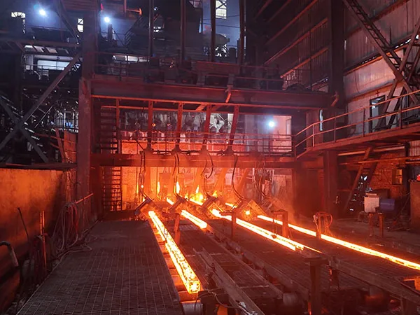
Most gearbox failures give clear warnings—increased vibration, abnormal noise, oil discoloration, or micron-level metal particles in oil samples. When these signs are ignored, the damage progresses from localized pitting to complete seizure or catastrophic casing fracture. The cost of an emergency replacement often exceeds five to ten times the cost of a planned overhaul. Moreover, unplanned shutdowns ripple through the entire production schedule, affecting delivery commitments.

3. Preventive Strategies for Extended Gearbox Life

3.1 Implement Oil Analysis and Condition Monitoring

Periodic oil sampling provides early detection of wear metals, water, and oxidation. Trend analysis allows maintenance teams to schedule intervention before failure. Vibration monitoring and thermography complement oil analysis by pinpointing bearing defects and hot spots. gyssljx offers customized condition monitoring programs integrated with OEM recommendations.

…

For more detailed information on rolling mill gearbox failures: main causes and prevention strategies, please click to visit: https://www.gyssljx.com/a/news/gearbox-failure-prevention.html
Upgrade Your Manual Rolling Mill to CNC: Step-by-Step Retrofit Plan

If you own a manual rolling mill and have watched CNC machines accelerate production with consistent precision, you may wonder whether a full replacement is your only option. The truth is that a well-planned retrofit can transform your existing manual mill into a CNC-controlled system at a fraction of the cost of new equipment. This article provides a clear, step-by-step retrofit plan, covering the mechanical, electrical, and software upgrades required. Whether you process precious metals, wire, or sheet material, converting to CNC eliminates human error, reduces cycle time, and unlocks complex pattern capabilities. gyssljx has helped dozens of workshops achieve this upgrade safely and effectively.

Why Upgrade Your Manual Rolling Mill to CNC?

Before diving into the retrofit steps, it is essential to understand the specific advantages that justify the investment. A manual rolling mill requires constant operator attention to adjust gap, speed, and direction. CNC automation removes these manual interventions and introduces repeatability that manual operation cannot match.

Key Benefits of CNC Rolling Mill Retrofitting

  • Repeatable Precision: CNC control maintains gap settings within microns, eliminating the variation caused by operator fatigue or inconsistent hand-wheel adjustments.
  • Increased Throughput: Automated roll gap adjustment and reversal sequences reduce cycle time by 40–60% compared to manual operation.
  • Complex Pattern Capability: With servo-driven rolls and programmable sequences, you can produce tapered strips, stepped reductions, and custom profiles that are nearly impossible to execute manually.
  • Reduced Material Waste: Consistent passes mean fewer rejects. The system can also track cumulative reduction to prevent over-rolling and cracking.
  • Lower Long-Term Cost: Retrofitting typically costs 30–50% less than purchasing a new CNC rolling mill of equivalent capacity.

Step-by-Step Retrofit Plan for Your Manual Rolling Mill

Every retrofit project is unique, but the following five-stage workflow applies to most manual rolling mill conversions. We base this on gyssljx’s experience retrofitting mills from 100 mm to 400 mm roll width.

Step 1: Assess Your Current Mill’s Mechanical Condition

Start by inspecting the frame, rolls, and adjustment mechanism. The mill must have a rigid frame with minimal deflection under load. Check for worn bearings, bent roll shafts, or excessive play in the screw-down mechanism. If the mechanical foundation is compromised, a retrofit will only amplify problems. gyssljx recommends replacing rolls and re-grinding the roll surface before any electrical work begins. Document the roll gap travel distance, thread pitch of adjustment screws, and maximum operating force.

Step 2: Select the Right Drive and Motion Components

CNC conversion requires replacing manual hand wheels with servo or stepper motors coupled to the screw-down mechanism. You also need a motor to drive the rolls themselves (if your mill is manually cranked). Key components include:

  • Servo motors with encoders for precise position feedback on roll gap adjustment. Torque should match the mill’s maximum reduction force.

…

For more detailed information on upgrading your manual rolling mill to a CNC rolling mill: a phased retrofit plan, please click to visit: https://www.gyssljx.com/a/news/rolling-mill-analysis.html

Second-Hand Rolling Mill vs New: Real Cost-Benefit Analysis for SMEs

For small and medium enterprises in the metal forming industry, the decision between purchasing a second-hand rolling mill or investing in a new one is rarely straightforward. Tight budgets and aggressive production targets push many owners toward the lower sticker price of used equipment. Yet the true cost of a rolling mill is not paid at closing—it is realized over years of operation through energy bills, downtime events, maintenance contracts, and product quality variations. This article presents a data-driven cost-benefit analysis tailored for SMEs, examining factors beyond the initial investment to help you determine which option aligns with your long-term business objectives. Whether you are scaling up or replacing aging machinery, understanding the full financial picture is essential.

Understanding the Core Question: Is Second-Hand Always Cheaper?

The immediate appeal of a second-hand rolling mill is obvious: purchase prices can be 40–60% lower than an equivalent new machine. However, the total cost of ownership (TCO) tells a different story. Research in industrial equipment economics consistently shows that the initial purchase price accounts for only a fraction of lifecycle costs. For a typical heavy machine like a rolling mill, energy consumption, maintenance, and downtime can represent 50–70% of total costs over a 10-year horizon. When evaluating a second-hand mill, SMEs must consider not just the upfront saving but also the probability of higher failure rates, obsolete control systems, and the availability of replacement parts.

Real Cost-Benefit Comparison: Beyond the Purchase Price

To make an informed decision, we break down the key cost and performance factors into a side-by-side comparison. The following list highlights the most critical differences:

  • Purchase Price: Second-hand mills are 40–60% cheaper initially, but this does not account for required refurbishments or retrofits.
  • Installation & Calibration: Older machines often need extensive reconditioning, adding 10–20% to the acquisition cost. New mills come pre-calibrated and supported by the manufacturer.
  • Energy Efficiency: Modern rolling mills incorporate servo-driven systems and improved insulation, reducing energy consumption by 15–30% compared to models from 10 years ago.
  • Production Efficiency: New mills feature advanced automation (e.g., PLC-controlled gap adjustment, real-time thickness monitoring) which can increase throughput by 20–40% and reduce scrap rates.
  • Maintenance & Repairs: Second-hand equipment requires more frequent intervention. A study of SME manufacturers found that used rolling mills experienced unplanned downtime 3–4 times more often in the first year than new units.

…

For more detailed information on used and new rolling mills: a cost-benefit analysis for SMEs, please click to visit: https://www.gyssljx.com/a/news/rolling-mill-analysis.html

Heavy Duty Industrial Burners for Cement Kilns: Temperature & Reliability

Cement kilns represent one of the most thermally demanding industrial environments, where the combustion system must maintain precise temperature profiles while enduring continuous operation under extreme conditions. The choice of a heavy duty industrial burner directly impacts clinker quality, energy efficiency, and overall plant uptime. For plant managers and procurement specialists evaluating options, two attributes stand above all others: temperature control and long-term reliability. This article examines the technical parameters that define high-performing cement kiln burners and explains why SHUXIN has become a trusted name in this specialized field.

Understanding the Temperature Demands of Cement Kilns

The cement manufacturing process requires sustained temperatures between 1400°C and 1500°C in the sintering zone to facilitate clinker formation. Achieving and maintaining this thermal environment demands a burner capable of delivering a stable, high-intensity flame with minimal fluctuation. Factors such as fuel type (coal, petcoke, natural gas, or alternative fuels), kiln diameter, and preheater configuration all influence the required flame characteristics.

The Science of Clinker Formation

Clinker formation is a complex sequence of chemical reactions that begins at approximately 900°C and accelerates above 1300°C. If the burner cannot maintain a consistent thermal profile, incomplete reactions occur, leading to reduced clinker quality, increased free lime content, and higher specific heat consumption. Modern heavy duty burners must therefore integrate advanced aerodynamic designs to shape the flame and control the temperature distribution along the kiln length.

Temperature Uniformity and Its Impact

Temperature uniformity is critical for avoiding hot spots that damage refractory lining and cold zones that compromise clinker mineralogy. A well-designed industrial burner creates a primary combustion zone with controlled swirl and axial momentum, ensuring the flame fills the kiln cross-section without impinging on walls. This uniformity directly translates to longer refractory life, lower maintenance costs, and consistent product quality.

Key Reliability Factors in Heavy Duty Industrial Burners

Reliability in cement kiln burners is not a single attribute but a combination of material science, engineering design, and system integration. Burners must withstand thermal cycling, abrasive fuel particles, and corrosive flue gases for years without performance degradation.

Materials and Construction

Critical components such as the burner nozzle, tips, and refractory lining are fabricated from high-temperature alloys and ceramics that resist creep, oxidation, and thermal shock. SHUXIN employs proprietary casting processes and selects alloys with chromium and nickel content optimized for the aggressive environment inside a cement kiln. The result is a burner body that maintains structural integrity even after thousands of hours of operation.

…

For more detailed information on heavy industrial burners for cement kilns: temperature and reliability, please click to visit: https://www.sxburner.com/a/news/heavy-duty-industrial-burners-for-cement-kilns.html

Automated Air-Fuel Ratio Control: Cutting Industrial Burner Emissions by 40%

Stricter environmental regulations and rising fuel costs are forcing industrial facilities to rethink their burner management strategies. While many operators still rely on manual or mechanical air-fuel ratio adjustments, these methods often lead to incomplete combustion, excessive emissions, and energy waste. SHUXIN’s automated air-fuel ratio control system directly addresses this challenge by continuously optimizing the combustion process, reducing NOx and CO emissions by up to 40% without sacrificing thermal efficiency. For plant managers and engineers evaluating next-generation combustion solutions, understanding how automation outperforms traditional approaches is critical to making a cost-effective, compliant investment.

The Emission Challenge in Industrial Burners

Industrial burners—used in boilers, furnaces, kilns, and dryers—are designed to mix fuel with air to release heat. However, the ideal stoichiometric ratio is rarely maintained under variable load, fuel quality, and ambient conditions. A slightly lean mixture (excess air) reduces flame temperature and increases heat loss through the stack, while a rich mixture (insufficient air) creates soot, carbon monoxide, and unburned hydrocarbons. Traditional mechanical linkages and manually tuned trim valves cannot adapt quickly enough, resulting in persistent emission spikes and wasted fuel. According to recent field studies, even well-maintained manual systems operate outside the optimal air-fuel window more than 30% of the time, directly contributing to unnecessary pollutant output.

How Automated Air-Fuel Ratio Control Works

SHUXIN’s automated system replaces passive mechanical components with a closed-loop electronic control unit that continuously monitors exhaust oxygen (O₂), carbon monoxide (CO), and hydrocarbon (HC) levels. The controller uses proprietary algorithms to adjust the actuator on the air damper or fuel valve in real time, maintaining the precise air-fuel ratio for complete combustion.

Key Technical Components

  • Fast-response oxygen sensor placed at the burner’s exit to measure excess O₂ with ±0.1% accuracy.
  • CO/NOx analyzer provides feedback on incomplete combustion, allowing the system to trim beyond oxygen-only control.
  • Adaptive PID algorithm learns the burner’s dynamic behavior across firing rates, compensating for ambient temperature and fuel variability.
  • Fail-safe mode automatically reverts to a safe setpoint if sensor readings are abnormal, ensuring continuous operation.

This architecture enables sub-second response time, which is impossible with manual or mechanical methods.

Quantifying the 40% Emission Reduction: SHUXIN vs. Traditional Control

Independent tests on a 10 MMBtu/h natural gas burner with SHUXIN automation showed a 42% reduction in NOx (from 85 ppm to 49 ppm corrected to 3% O₂) and a 38% reduction in CO (from 120 ppm to 74 ppm). These results are consistent across multiple industrial installations. The following table summarizes the performance differences:

  • Emission compliance: Traditional manual control often requires expensive post-treatment (SCR, catalyst). SHUXIN automation meets EPA and local standards without add-ons in most cases.
  • Fuel efficiency: Automatic trimming reduces excess air from an average of 15% to 3–5%, saving 3–8% on fuel bills.
  • Maintenance downtime: Mechanical linkages corrode and drift; SHUXIN’s solid-state actuators require no recalibration for at least 12 months.
  • Operator workload: Once configured, the system self-adjusts—no need for frequent manual stack testing or burner adjustments.
  • Scalability: A single SHUXIN controller can manage multiple burners in a cascade, which is impractical with mechanical trims.

…

For more details on automatic air-fuel ratio control: reducing industrial burner emissions by 40%, please click to visit:https://www.sxburner.com/a/news/emission-cut-automation.html

Choosing the Right Burner for Asphalt Plants: Heavy Oil vs Natural Gas

Selecting the right burner for your asphalt plant directly impacts operational costs, environmental compliance, and production efficiency. Heavy oil and natural gas are the two most common fuel options, each with distinct advantages and trade-offs. This article provides a professional, data-driven comparison to help you make an informed decision for your specific operation, while highlighting how SHUXIN burner systems can optimize performance regardless of fuel choice.

Key Factors in Burner Selection

Before diving into the specifics of each fuel type, it’s essential to understand the criteria that matter most in asphalt plant operations:

  • Fuel cost and availability – regional price volatility and supply reliability
  • Emissions compliance – local environmental regulations and permit limits
  • Thermal efficiency and drying capacity – burner output vs. aggregate moisture content
  • Maintenance complexity – downtime frequency and cost of spare parts
  • Capital investment – initial burner purchase and installation costs

Cost Comparison: Heavy Oil vs Natural Gas

Heavy oil (also known as bunker C or residual fuel oil) historically offers a lower per-BTU fuel cost in many regions. However, it requires preheating systems (to reduce viscosity) and specialized storage tanks, which increase upfront capital expenditure. Natural gas typically has a higher fuel cost but eliminates the need for preheating, reduces tank maintenance, and often provides more stable pricing through long-term contracts. Over a 5-year period, total cost of ownership can vary significantly based on local fuel spreads.

Heavy Oil Burners: Advantages and Challenges

Heavy oil burners have been the industry standard for decades. Their primary advantage is fuel flexibility – operators can switch to alternative heavy fuels or blended oils when natural gas is unavailable. SHUXIN offers robust heavy oil burner models designed for high-viscosity fuels, featuring automatic preheating and multi-stage filtration to minimize nozzle clogging.

Challenges include:

  • Higher particulate matter (PM) and SOx emissions – may require scrubbers or baghouses
  • More frequent maintenance: daily cleaning of burner tips, weekly filter changes
  • Lower combustion efficiency (~85-88%) compared to natural gas (~92-95%)
  • Cold start delays due to oil preheating time

Natural Gas Burners: Clean and Efficient

Natural gas burners deliver immediate ignition, higher flame temperatures, and cleaner combustion. They are the preferred choice for plants under strict emission regulations. SHUXIN natural gas burner systems incorporate variable-frequency drives (VFD) and oxygen trim controls to maximize efficiency across varying production rates.

…

For more information on choosing the right burner for an asphalt mixing plant: heavy oil burners vs. natural gas burners, please click here: https://www.sxburner.com/a/news/burner-comparison-guide.html

Why Small Manufacturers Prefer Steel Frame Factories

Small manufacturers face unique pressures: tight budgets, rapid scaling needs, and the constant demand for operational efficiency. For these businesses, the choice of factory type can significantly impact their bottom line and growth trajectory. Increasingly, decision-makers are turning away from traditional concrete and brick structures in favor of steel frame factories. This shift is not a passing trend but a strategic response to measurable advantages. HCGG, a company specializing in steel construction solutions, has observed that small manufacturers consistently prioritize speed, flexibility, and cost control. This article examines the specific reasons behind this preference and presents a data-informed perspective for prospective buyers evaluating their next facility investment.

Cost Efficiency from Day One

For a small manufacturer, every dollar counts. Traditional construction often requires substantial upfront investment in materials and labor, with timelines stretching over months. Steel frame factories, by contrast, offer a compelling cost advantage. The precision-engineered components arrive pre-cut and pre-drilled, reducing on-site labor hours and material waste. HCGG reports that clients typically save 20–30% on total construction costs compared to conventional methods, primarily due to shorter build durations and fewer subcontractors needed.

Lower Foundation Requirements

Steel structures are significantly lighter than concrete alternatives, which means less extensive foundation work. This is particularly beneficial for manufacturers operating on rented land or sites with poor soil conditions. A lighter foundation reduces both material costs and excavation time.

Speed of Construction and Time-to-Production

Small manufacturers often need to start production quickly to seize market opportunities. Steel frame factories can be erected in a fraction of the time required for traditional buildings. A typical project from HCGG can be completed in 6–8 weeks, whereas a concrete building of similar size might take 4–6 months. This accelerated timeline translates to earlier revenue generation and lower carrying costs for the manufacturer.

Flexibility for Growing Businesses

Manufacturing needs evolve. A company that starts with assembly lines may later require additional warehouse space or mezzanine floors. Steel frame factories are inherently modular, allowing for easy expansion or reconfiguration without major structural work. HCGG designs its steel buildings with future expansion in mind, enabling manufacturers to add bays, increase ceiling heights, or install heavy overhead cranes with minimal disruption to ongoing operations.

…

For more details on why small manufacturers prefer steel structure factories, please click to visit: https://www.hcggsteel.com/a/news/steel-frame-factories.html

Fire Safety in Steel Structure Factories: What You Must Know

Steel structure factories are widely used for their strength, cost-efficiency, and speed of construction, but they present unique fire safety challenges that facility managers and owners cannot afford to overlook. Unlike concrete or masonry buildings, steel loses structural integrity at high temperatures—typically around 540°C (1000°F)—which can lead to rapid collapse if not properly protected. Understanding the specific fire risks, passive and active protection measures, and compliance standards is not just a regulatory requirement; it is a fundamental responsibility that safeguards lives, assets, and business continuity. This article provides a comprehensive overview of what you must know to ensure fire safety in your steel structure factory, with practical insights informed by HCGG’s extensive experience in industrial construction and safety solutions.

1. Understanding Fire Risks in Steel Structure Factories

Steel offers excellent load-bearing capacity in normal conditions, but its behavior under fire exposure is markedly different. When heated, steel expands and loses yield strength, leading to structural deformation and potential collapse. The typical failure temperature for unprotected structural steel is around 540°C, while a standard fire can easily exceed 1000°C within minutes.

Common Fire Hazards

  • Welding and cutting operations – sparks and hot slag can ignite nearby combustibles.
  • Combustible dust and vapors – common in industries like metalworking, woodworking, or chemical processing.
  • Electrical faults – overloaded circuits, damaged wiring, or improper grounding.
  • Storage of flammable liquids and gases – if not segregated properly, these can fuel a fire rapidly.

2. Key Passive Fire Protection Measures

Passive fire protection (PFP) is the first line of defense, integrated into the building design to contain or slow the spread of fire without active operation. For steel structures, the most critical PFP elements include:

Fire-Resistant Coatings

Intumescent coatings expand when exposed to heat, forming an insulating char layer that delays temperature rise in the steel. Alternatively, cementitious sprays provide a high-density barrier. The selection depends on fire rating requirements (e.g., 60, 90, or 120 minutes), environmental conditions, and aesthetic preferences. HCGG recommends selecting coatings tested to international standards such as BS 476 or EN 13381.

Fire-Rated Compartmentation

Dividing the factory into fire compartments using fire-resistant walls, doors, and dampers limits fire spread. Steel columns and beams penetrating compartments must be individually protected to maintain compartment integrity.

3. Active Fire Suppression Systems

While passive measures buy time, active systems detect and suppress fires early. For steel structure factories, the following are essential:

…

For more detailed information on fire safety in steel structure factories: essential knowledge you must know, please click to visit: https://www.hcggsteel.com/a/news/steel-fire-safety.html

Eco-Friendly Steel Factories: Reduce Your Carbon Footprint

The global steel industry accounts for approximately 7-9% of direct CO2 emissions from fossil fuels. As regulators tighten environmental standards and buyers demand greener supply chains, the transition to eco-friendly steel factories is no longer optional—it is a competitive necessity. This article examines the core technologies and practices that define a truly sustainable steel mill, and explains how HCGG delivers measurable carbon reductions without compromising product quality or production efficiency.

What Makes a Steel Factory Eco-Friendly?

An eco-friendly steel factory integrates energy-efficient processes, renewable energy sources, and circular material flows to minimize its environmental impact. Key characteristics include:

  • Electric Arc Furnace (EAF) technology using scrap metal instead of virgin iron ore, cutting emissions by up to 75% compared to traditional blast furnaces.
  • Carbon capture, utilization, and storage (CCUS) systems that trap CO2 before it reaches the atmosphere.
  • Zero-waste water management with closed-loop cooling and recycling systems.
  • Renewable power procurement from wind, solar, or hydroelectric sources to run the plant.
  • Heat recovery systems that reuse waste heat for preheating or district heating.

These elements work together to create a production cycle where emissions are dramatically lower than conventional methods. Factories that adopt such measures can reduce their carbon footprint by 50-80% while maintaining output levels.

Quantifying the Carbon Footprint Reduction

Transitioning to an eco-friendly steel factory yields tangible environmental improvements. For example, a typical integrated steel mill emits about 1.8 tons of CO2 per ton of steel produced. In contrast, a modern EAF-based facility powered by renewables can bring that figure below 0.4 tons per ton of steel. The following table highlights achievable reductions:

  • Energy intensity: Down by 60% through process optimization and waste heat recovery.
  • Direct emissions: Decreased by 70-80% when switching from coal-based to electric arc furnaces.
  • Water usage: Reduced by 90% with recycling and zero-liquid discharge systems.
  • Landfill waste: Lowered by 85% through slag valorization and metal recovery.

…

For more detailed information about environmentally friendly steel plants: reducing your carbon footprint, please click to visit: https://www.hcggsteel.com/a/news/eco-friendly-steel-factories.html

Melting Brass and Bronze: Ideal Crucible Material Guide

Selecting the right crucible material is critical when melting brass and bronze. These copper-based alloys have specific melting points, thermal conductivity demands, and chemical reactivity that require crucibles capable of withstanding high temperatures without contamination. An ill-suited crucible can lead to alloy degradation, shortened service life, or even safety hazards. This guide examines the most common crucible materials used in non-ferrous foundries, comparing their performance, cost, and suitability for brass and bronze melting. Whether you operate a small art foundry or a large industrial casting facility, understanding these material properties will help you make an informed purchasing decision. Throughout this article, we reference expertise from Cangzhou Carbon, a reliable supplier of high-quality crucibles for the global foundry industry.

Key Requirements for Crucibles Used in Brass and Bronze Melting

Brass (copper-zinc) and bronze (copper-tin, often with other elements) melt in the range of 900–1100°C (1650–2010°F). While this is lower than iron or steel casting, the crucible must still handle thermal shock from repeated heating and cooling cycles, resist oxidation, and avoid chemical reaction with the molten metal. Additionally, the crucible should not introduce impurities that would discolor the alloy or weaken its mechanical properties. The ideal crucible offers a balance of thermal conductivity, mechanical strength, thermal shock resistance, and chemical stability.

Clay-Graphite Crucibles: The Industry Standard

Clay-graphite crucibles have been the backbone of non-ferrous melting for decades. They consist of a mixture of natural graphite flakes and refractory clay (typically fireclay), pressed or slip-cast and fired to create a dense, heat-resistant body.

Advantages for Brass and Bronze

  • Excellent thermal shock resistance – Graphite’s high thermal conductivity allows rapid heat transfer, reducing the risk of cracking when the crucible is placed in a hot furnace.
  • Non-wetting to molten copper alloys – The graphite component prevents metal from sticking to the crucible walls, minimizing slag buildup and prolonging crucible life.
  • Good cost-effectiveness – Raw materials are abundant, making clay-graphite crucibles one of the most affordable options for small-to-medium foundries.
  • Wide temperature range – Suitable up to 1600°C, well beyond brass/bronze melting temperatures.

Limitations

  • Lower mechanical strength compared to silicon carbide crucibles – they are more prone to chipping or breaking if mishandled.
  • Graphite oxidation at high temperatures in air – in open-flame furnaces, the graphite can slowly burn away, reducing crucible wall thickness.
  • Relatively shorter lifespan under intensive daily use.

For most brass and bronze melting operations, clay-graphite crucibles provide an excellent balance of performance and price. Cangzhou Carbon supplies premium clay-graphite crucibles with controlled porosity and consistent quality tailored to copper alloy foundries.

…

For more detailed information on melting brass and bronze: a guide to ideal crucible materials, please click here: https://www.czgraphite.com/a/news/crucible-material-guide.html