Eliminate Manual Flipping: Automated Rotator for Tower Fabrication
Imagine a fabrication floor where workers no longer risk injury by manually flipping heavy tower sections, where cycle times shrink by half, and where every rotation is perfectly aligned for welding and coating. This is not a distant vision—it is the reality delivered by an automated rotator system. For manufacturers of transmission towers, wind turbine towers, and other large cylindrical structures, eliminating manual flipping is not just an operational upgrade; it is a strategic imperative. BOTA has engineered a solution that redefines workflow efficiency and worker safety, making cumbersome manual handling a relic of the past.
Challenges of Manual Flipping in Tower Fabrication
Traditional tower fabrication relies on overhead cranes and manual labor to rotate heavy steel sections—often weighing several tons—during welding, grinding, and coating processes. This method introduces multiple pain points:
- Safety hazards: Workers must physically guide and stabilize unstable loads, leading to frequent near-misses and crush injuries.
- Low productivity: Each flip requires crane setup, repositioning, and coordination among multiple workers; a single rotation can take 15–30 minutes.
- Quality inconsistency: Manual positioning often results in misalignment, requiring rework and compromising weld integrity.
- Workflow bottlenecks: The entire production line pauses during flipping operations, creating idle time for downstream processes.
These challenges drive up operational costs and limit throughput, especially as tower sizes grow to meet wind energy and infrastructure demands. A paradigm shift is needed—one that an automated rotator delivers.
How an Automated Rotator Transforms the Workflow

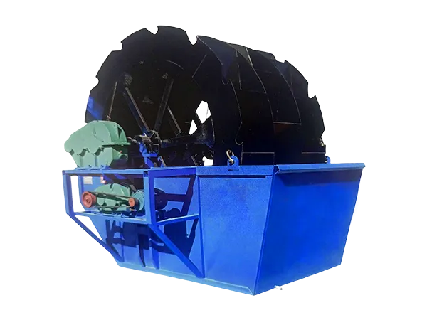
An automated rotator for tower fabrication is a robust, programmable system that grips, lifts, and rotates tower sections around a central axis with minimal human intervention. BOTA’s design integrates servo-driven rollers, hydraulic clamps, and a PLC-based control interface to enable seamless 360-degree positioning at variable speeds. Key operational improvements include:
Elimination of Crane Dependency
Once the tower section is loaded onto the rotator (often via a simple transfer cart), all subsequent rotations occur without overhead crane involvement. This frees up crane capacity for other critical tasks and eliminates the coordination delays associated with shared equipment.
…
For more information about automatic rotators for manufacturing towers that eliminate the need for manual inversion, please click here:https://www.bota-weld.com/en/a/news/automated-rotator-for-tower-fabrication.html